August 2023: A reduced version of this post was posted in a previous version of this blog. Diagrams and details have been added in this new version.
In the original 5 and and a half posts of the blog series RVV in a Nutshell, we presented the basics of RISC-V Vector extension (RVV 1.0), but even after this overview some aspects of this large extension can still seem difficult to apprehend.
This post is part of a few extra posts to provide more details about RISC-V Vector extension (Vector Register Groups, Element Groups).
In this post we detail how to interpret the various components of a RVV assembly instruction.
Overview
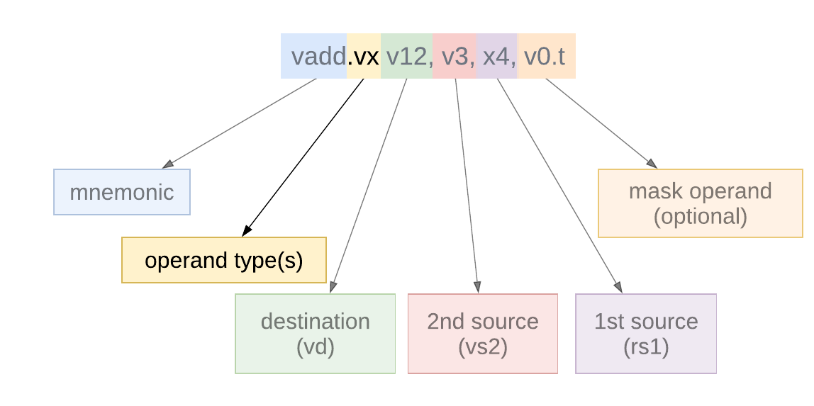
We will draw some generalities from a practical example: a masked integer vector-scalar addition vadd.vx v12, v3, x4, v0.t.
The following diagram illustrates the 6 main components of any RVV assembly instruction. Most of those components have numerous variants and some of them are optional (e.g. the mask operand).
Mnemonic
The first component is the mnemonic which describes which operation should be performed by the instruction (e.g. in our case vadd will perform a vector add).
The mnemonic often describes the destination type: for example vadd is a vector add with a single-width destination, while vwadd is a widening vector add (the destination elements are wider than the main input operands) and vmadc is a vector addition with carry returning a mask of output carries.
Operand type(s)
The second component is the operand type(s). It describes on what type of operand(s) the operation is performed. The most common is .vv (vector-vector) which often means that the instruction admits at least two inputs and both are single-width vectors (non widening operation).
The list of various possibilities includes:
.vv operation between two (or three) single-width vectors, e.g.
vmul.vv.wv operation between two (or three) vectors,
vs1is single-width whilevs2andvdare wide operands/destinations (EEW=2*SEW), e.g.vwmacc.wv.vx / .vf operation between one or multiple vector(s) and a scalar (read from a general purpose register: x or floating-point register f), e.g.
vfadd.vf, the scalar operand is splat to build a vector operand and added to each active vector element.wx / .wf: operation between a scalar and a wide second vector operand, e.g.
vfwadd.wf.vi operation between one or multiple vector(s) and an immediate. The immediate is a 5-bit1 wide value encoded in the opcode
rs1/vs1field, e.g.vsub.vi v2, v3, 7.vs: operation between a vector and a single element (scalar) contained in a vector register, e.g.
vredsum.vs(the single scalar is used to carry the reduction accumulator). In vector crypto, .vs defines an operation between a vector and a single element group2..vm: operation between a vector and a mask, e.g.
vcompress.vm.v: operation with a single vector input, e.g.
vmv2r.v, may also be used for vector loads (which have scalar operands for the address on top of a single data vector operand:vle16.v..vvm / .vxm / .vim operation vector-vector / vector-scalar / vector-immediate with a mask operand (e.g.
vadc.vvm, addition between two vectors with an extra mask operand used as an input carry vector)
The conversions constitutes a category of their own for the operand types, because the mnemonic suffix describes: the destination format, the source format, and the type of operand. For example vfcvt.x.f.v is a vector (.v) conversion from floating-point element (.f) to signed integer (.x) result elements. .xu is used to indicate unsigned integers, .rtz is used to indicate a static round-towards-zero rounding mode.
Destination and source(s)
In the assembly instruction, destination and sources follows the mnemonic. The destination is the first register to appears, followed by one or multiple sources.
Each of those element encodes a register group. The destination and source operands register groups are represented by the first register in the group (for example if LMUL=4, then v12 represents the 4-wide register group v12v13v14v15). Thus the actual register group depends on the assembly opcode but also on the value of vtype: it is context sensitive. Most RVV operations have a vector destination, denoted by vd, some may have a scalar destination (e.g. vmv.x.s with a x register destination or vfmv.f.s with a f register destination) and others have a memory destination such as the vector stores, e.g. vse32.v.
There can be one or two sources: vs2 and vs1 for vector-vector instructions. If the operations admits a scalar operand, or an immediate operand then vs1 is replaced by rs1 (respectively imm), e.g. vfadd.vf v4, v2, ft3. Vector loads have a memory source, e.g. vloxei8.v vd, (rs1), vs2 [, vm] which has a scalar register as address source and a vector register as destination source.
RVV defines 3-operand instruction, e.g. vmacc.vv. For those operations the destination register vd is both a source and a destination: the operation is destructive: one of the source operand is going to be overwritten by the result.
Mask operand
Most RVV operation can be masked. When an operation is masked only a subset of body elements are active and operated upon. In such case an extra vector register operand appended at the end of the assembly instruction is used as a mask to determine which elements are active and which elements of the result will be copied from the old destination value or filled with a predetermined pattern (the behavior is selected by the vconfig.vta tail policy flag). RVV 1.0 only supports the register v0 as a mask operand and true bit as active mask value: the element is considered active if the bit at the corresponding index is set to 1 in v0, and inactive if it is 0. This is what is encoded by the last operand of our example: v0.t (for v0 "true as active"). If this last operand is missing, then the operation is unmasked (all body elements are considered active). v0.t is usually encoded by clearing bit 25 of the opcode, when this bit is set, the operation is unmasked.
Note: The 32-bit opcodes of RVV 1.0 are too small to allow the explicit encoding of a mask operand (other than v0) or the encoding of the active encoding (true / false). A future RVV extension might rely on 64-bit instructions to encode more information, including provide more flexibility when it comes to specifying mask operand and policy.
More information on the operation with mask can be found in this post of the original series: RVV in a nutshell (part 3): operations with and on masks.
Conclusion
We hope this post has shed some lights on the syntax of RISC-V Vector assembly instructions. To get an overview of RVV you can check our series or subscribe to get notified of future posts:
Updates:
August 26th 2023: new version with diagrams for each instruction element and more details
August 27th 2023: fixing scalar operand (v4 → x4, vs1 → rs1) in example and diagrams. Thank you to Jack O’Connor for pointing it out.
Reference:
There are some instructions which consider only a subset of the 5-bit immediate or extend it (e.g. Zvkb’s vror.vi instruction admits a 6-bit immediate useful for 64-bit element rotations)
See this post:
RISC-V Vector Element Groups
RISC-V Vector extension has defined multiple ways to organize vector data over one or multiple vector registers. In this previous blog post we presented the concept of vector register groups defined by RVV 1.0: the capacity to group together multiple vector registers into a meta (larger) vector register which can be operated on as a single operand by mo…


I don't know if you've commented on this, but there's a difference in the order operands are specified for scalar vs. vector assembly ops, which could cause some confusion. For example,
for scalars, there is
sub rd, rs1, rs2 does rs1-rs2 -> rd
but for vectors, there is:
vsub.vx vd, vs2, rs1, vm does vs2[i]-rs1 -> vd[i] and
vrsub.vx vd, vs2, rs1, vm does rs1-vs2[i] -> vd[i]
It's somewhat counter-intuitive until you are aware of it, but I can see why vectors are specified this way.
In the example "vadd.vx v12, v3, v4", v4 needs to be a scalar register like x4 no?